Drawing a Colored Equilateral Triangle using Tao and C#
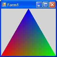 |
Here is our goal for this simple tutorial. We will draw
a single triangle defined as an equilateral
triangle with a unit length base from zero to one on the x-axis.
We will assign a different color to each vertex and let the graphics
hardware interpolate
the color across the triangle during its rasterization.
Nothing fancy here, we just want to go through the steps to install Tao
and create a new application that uses it. |
Setting up Tao and working with .NET
Follow the initialization steps to install Tao and configure your .NET application. The tutorial is provided here.
Initializing a OpenGL context
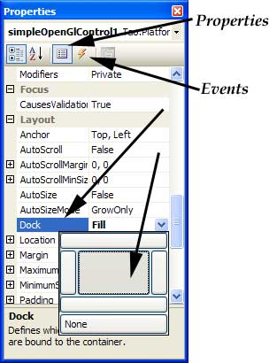 |
OK, Open up Form1.cs in the Designer. From the Toolbox, select the
SimpleOpenGlControl and drag it on top of the Form. For this application, we
want the OpenGL window to fill the form, so with the control selected, open
the Properties window find the Dock item and choose DockStyle to be Fill.
Let me take a moment to point out two key buttons on the Property
window. The Properties page allows you to set various attributes about
the control. Most of these affect the appearance. The lightning bolt displays
the Events page. We will use this in a minute to specify a method that
should be called everytime the control needs to be re-painted. This is also
where you can state routines to be called whenever a key is pressed or the mouse
is clicked within this window or control. Different
controls will have different properties and different events.
Select the BackColor property and choose a color of your liking besides black.
Also note that the SimpleOpenGlControl has a property group called OpenGL Properties
which control various context creation values. We will use the defaults. If
you try to run the application at this point you will receive an error stating
that "No device or rendering context is available!".
 |
This is because
we haven't actually initialized the OpenGL context. The best place for this
is in the constructor for Form1 after the SimpleOpenGlControl instance (called
SimpleOpenGlControl1 unless you modified the name on the Properties page) is
created. But you say, we have not created anything in Form1. The only code is
a call to InitializeComponent. With the introduction of .NET 2.0, the concept
of partial classes was added to C#. |
You will note below, that Form1 is declared
as a partial class. This just allows us to split the definition of the class
across mulitple files. The InitializeComponent method is defined in the file
Form1.designer.cs. If you open this you will see that an instance of SimpleOpenGlControl
is declared and created. |
So, add a call to the InitializeContexts method after
the call to InitializeComponent in Form1.cs. Note, you should also call DestroyContexts
in the Dispose method to clean up after yourself once the program terminates.
Visual Studio placed the Dispose method in the Form1.designer.cs
file, and we really should not touch this file, lest we disturb the Designer.
However, we can capture an event that let's us know that the form is either closing or has closed. At this point you can run the program and it should
present a window with either a black background or junk. This window has a valid
OpenGL contex. However, the background color that we set in the Designer did
not show up. We now need to control what is drawn into this window and when to clear
it to our background color.
Drawing our Triangle
Whew!!! We now have OpenGL exposed and ready to be used in our application.
Not all of those steps will be necessary with your next OpenGL application.
We just need to add the References, add the SimpleOpenGlControl to our Form
and initialize it.
The only method in our Form currently is a contructor. It does not do anything
(e.g. interesting. It does maximize to full screen, minimize and close). Finally,
we'll clear the window and draw a triangle. We'll do so by adding an event handler
to the SimpleOpenGlControl's Paint event. In the Designer, select the SimpleOpenGlControl
and then select the Events page in the Properties window. Beside each event,
you can select an existing method that should be called for this event. We haven't
written ours yet. Visual Studio helps you by providing a stub routine with the
correct protocol. Double click the Paint event:
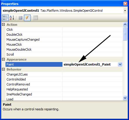
This will place you in the Code View for Form1 with a new method called simpleOpenGlControl1_Paint.
We will not worry about the arguements to this method (usually ever). Inside
this method is where we want to draw our triangle. Insert the code shown below:
23 private void simpleOpenGlControl1_Paint(object sender, PaintEventArgs e)
24 {
25 //
26 // Clear the contents of the display
27 //
28 Gl.glClear(Gl.GL_COLOR_BUFFER_BIT);
29 //
30 // Tell OpenGL that the vertices we are about to give it should
31 // be grouped into a set of triangles.
32 //
33 Gl.glBegin(Gl.GL_TRIANGLES);
34 // Set the current color for the next vertex.
35 Gl.glColor3f(1.0f, 0.0f, 0.0f);
36 // Specify the world-space location of the next vertex.
37 Gl.glVertex2d(0.0, 0.0);
38 // Set the current color for the next vertex.
39 Gl.glColor3f(0.0f, 1.0f, 0.0f);
40 // Specify the world-space location of the next vertex.
41 Gl.glVertex2d(1.0, 0.0);
42 // and so on.
43 Gl.glColor3f(0.0f, 0.0f, 1.0f);
44 Gl.glVertex2d(0.5, 0.867);
45 //
46 // Let OpenGL know that that was the last vertex.
47 // This is where the draw will actually happen.
48 //
49 Gl.glEnd();
50 }
|
Let's walk thru this. The comments are rather self-descriptive, but we basically
have two tasks: 1) clear the colors from the previous draw cycle and 2) draw
a single triangle consisting of three vertices. We change the color before each
vertex.
 |
Since OpenGL is a big state machine, the color really just sets a state
variable. It is when the vertex is defined that the color (as well as the normal,
texture coordinates, etc.) are gathered and shipped down to the graphics card
for this vertex. |
Build and run the application. This is what you should see:
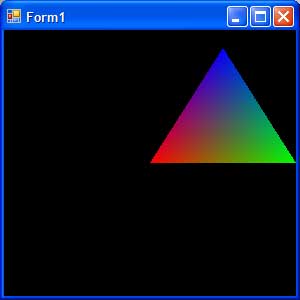
Not our desired result. While we specified the geometry, we did not specify
the camera or our view of the triangle. For our application, we just need a
simple 2D orthographic projection.
Add the following (line 29) to your code:
28 Gl.glClear(Gl.GL_COLOR_BUFFER_BIT);
29 Gl.glOrtho(0.0, 1.0, 0.0, 1.0, -1.0, 1.0);
30 //
31 // Tell OpenGL that the vertices we are about to give it should
|
This tells OpenGL that the existing viewport should map from zero to one in
the x-axis, zero to one in the y-axis and -1 to 1 in
the z-axis. Why these coordinates? The mapping is a
bounding box of the triangle, allowing us to see the entire triangle. The z-axis does not concern us, but
we need to tell OpenGL a range simply because it can not represent -infinity
to infinity. Our z-coordinates are all zero (glVertex2d sets them to zero for
us), so we just need have a range that include zero. Run the program. Does it
work? Move another window over the top of it to force the Paint event to occur
again. Did it go black? What happened?
The call to glOrtho we added modifies the OpenGL state. In this case it modifies
one of OpenGL's matrices. In the initial state of OpenGL this would modify the
current (or top-most) ModelView matrix. It was initially the identity matrix,
glOrtho mulitplied it by the orthographic projection matrix to yield the orthographic
projection matrix. OK, so you think the problem is that we should have set OpenGL's current projection
matrix. Well that too is initially the identity matrix and all OpenGL does with
these is multiply them together. Hence, we should have still gotten - you guessed it - our
desired orthographic projection matrix. So it should have worked. Why didn't
it?
The problem is that glOrtho modifies the matrix rather
than setting it. If we had only called the Paint event once, things would have
worked fine. The Paint event may fire several times, each time multiplying the
orthographic projection matrix into the last result. We eventually end up with
... Hmm, that is an interesting question. Maybe a future homework.
OK, let's fix this. Simply solution, reset the matrix to the identity matrix each time Paint is called. In general, this is dangerous since you do not know
which matrix is current and what the OpenGL state is currently. To be more picky,
we should encapsulate our objects to be drawn in their own class, allow for
other objects to be added etc. For now, add line 29 below, but remember this is
not very good programming practice:
28 Gl.glClear(Gl.GL_COLOR_BUFFER_BIT);
29 Gl.glLoadIdentity();
30 Gl.glOrtho(0.0, 1.0, 0.0, 1.0, -1.0, 1.0);
31 //
32 // Tell OpenGL that the vertices we are about to give it should
|
Build and Run and viola, we have our desired image. Or do we? One of the problems
in developing graphical application is the lack or difficulty of testing. Your
homework will ask you to change some settings and examine the result more closely.
Oh, what about the background color. Well, the SimpleOpenGlControl is not fully
functional. The BackColor property is for its base class and the control just
does not do anything with it. We can fix that. Insert the following lines of
code in the Form1 constructor:
13 InitializeComponent();
14 simpleOpenGlControl1.InitializeContexts();
15 //
16 // Propogate the UserControl's BackColor over to OpenGL's clear color.
17 //
18 System.Drawing.Color backColor = simpleOpenGlControl1.BackColor;
19 Gl.glClearColor((float)backColor.R / 255.0f,
20 (float)backColor.G / 255.0f, (float)backColor.B / 255.0f, 1.0f);
|
That should wrap up this tutorial. Please let me know of any misspelligs or
if I ain't used very good grammer.
Last modified:
September 17, 2007 10:38 AM