|
1
|
|
|
2
|
- Overview
- Military Objective
- ConOps
- What You Will See Today
- Technical Approach
- Performance
- Future Plans
- Discussion
|
|
3
|
|
|
4
|
|
|
5
|
- Hand-placed set of pre-configured sensor nodes at known locations
- System detects an intruder
- System classifies intruder as one or none of known intruder types
- System tracks an intruder as it moves past different sensors
- System routes intrusion messages through network to relay
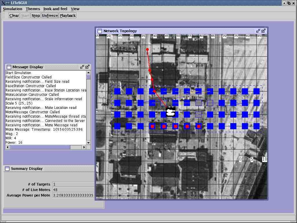
- System visualizes location of intruder on computer attached to relay
|
|
6
|
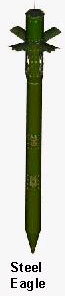
- Soldier Carrying “Gun”
- Walks/runs across line on trails
- Walks through sensor field
- Walks concurrently with another soldier
- Car
- Runs across line on trails at 5-20mph
- Person
- After MIR motes are added to line,
- Walks across line on trail
- Robustness
- Several motes in a region are turned off & then on again
- Some motes are displaced
|
|
7
|
- Overview
- What You Will See Today
- Technical Approach
- Model of Network & Intruders
- Classification Concepts &
Design
- Sensors and Middleware
- Performance
- Future Plans
- Discussion
|
|
8
|
|
|
9
|
- Intruders Types
- Dismounts
- Soldier (person carrying metallic
objects)
- Civilian (not carrying metallic
objects)
- Vehicles
- Car
- Tank (for future classification
types)
- Goal
- Minimize false positives &
false negatives via experimentally-validated mathematical models of
intruders & classification based on multiple “cheap” signal
parameters
|
|
10
|
- A centralized, resource-rich solution
- Each sensor classifies intruders
independently
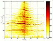
- Sample Concept: each intruder
type has a unique, sophisticated
time-frequency signature
|
|
11
|
- A distributed, dense, resource-poor solution
- Multiple sensors coordinate,
each with multiple modalities
- Sample concept: each intruder
type has unique influence field
- Our field experiment involves
- Target classification by
magnetometer & MIR signatures
- Tracking & counting (even
concurrent) intruders
- ~$40-50K for comparable range
and detections
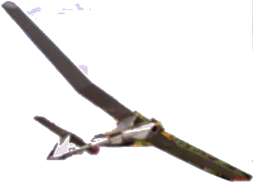
- Deployment via UAV; relative
cost & risk lower
- Focus on middleware aspects
|
|
12
|
- Network formation, routing (UT)
- Time synchronization (Iowa)
- Local matched filter (OSU)
- Regional matched filter
(OSU)
- Snapshot (OSU)
- Visualization (KSU)
- Key Technical Challenge
- Reliable delivery is critical
for all services
- Design space involves tuning many parameters
- Backoff interval selection,
network diameter load distribution, per hop reliability
- Involves tradeoffs with accuracy & delay
|
|
13
|
- Overview
- What You Will See Today
- Technical Approach
- Performance
- Future Plans
- Discussion
|
|
14
|
|
|
15
|
- In future deployments, we expect the density to be far less & the
cost/energy budget to scale much better than you will see today
- This will be achieved by
- Using better, alternative, and additional sensors,
- Incorporating detection of other local features, and
- Systematically thinning the line(s)
|
|
16
|
- Overview
- What You Will See Today
- Technical Approach
- Performance
- Future Plans
- Discussion
|
|
17
|
- Reduce density of line while controlling accuracy :
- use better magnetometer &
other sensors
- refine local matched filter to
use other features, i.e., signal amplitude
- correlate observations across
multiple lines
- Deal with longer coverage area,
particularly end-to-end reliability:
- power transmission control,
interference, altitude issues
- reliable routing for different
traffic patterns
- Refine intruder tracking & network health visualization detection:
- further refine outlier
detection
- Incorporate Power management, Localization, Data aggregation
|
|
18
|
- Current magnetometer gets magnetized over time
- circumvented by hardware reset circuitry
- Composition, testing, & monitoring tools need further development
- “Byzantine” motes are a serious issue for middleware services
- under low-power motes do not fail gracefully
- sensor debonding can yield unpredictable behavior
- Architecture for 1km -- 100km scale is best developed in context of
application scenario
|
|
19
|
|

 Notes
Notes